![]()
![]()
![]()
 (at ???)
 (at ???)
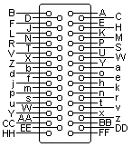
50 PIN M/50 MALE at ???.
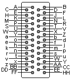
50 PIN M/50 FEMALE at ???.
| Pin | Return | Dir | Description | Active State |
|---|---|---|---|---|
| CC | EE | Ready | High | |
| Y | AA | On Line | High | |
| E | C | Demand | High | |
| j | m | Data Strobe | High | |
| B | D | Data 1 | n/a | |
| F | J | Data 2 | n/a | |
| L | N | Data 3 | n/a | |
| R | T | Data 4 | n/a | |
| V | X | Data 5 | n/a | |
| Z | b | Data 6 | n/a | |
| n | k | Data 7 | n/a | |
| u | w | Data 8 | n/a | |
| z | BB | Parity | n/a | |
| d | f | Ident 0 | n/a | |
| a | c | Ident 1 | n/a | |
| v | x | Interface Verify | Low | |
| HH | K | +5 VDC (Test) | High | |
| r | t | Parity Error | High | |
| M | P | Bottom of Form | High | |
| S | U | Top of Form | High | |
| p | s | Paper Instruction | High | |
| A | H | Buffer Clear | High | |
| W | Y | Paper Moving | High | |
| FF | DD | Paper Moving | High | |
| e | h | Not VFU | High |
Note: Direction is Host (Computer) relative Peripheral (Printer).
Note: Return is Ground signal for Unbalanced and the Negative Signal for Balanced.
Contributor: Joakim Ögren
Source:
?
Copyright © The Hardware Book Team 1996-2001.
May be copied and redistributed, partially or in whole, as appropriate.
Document last modified: 2001-06-08