Issue #1: After I got my Agenda VR3 and build my development environment, after
few days I was in trouble: Each day must charge and change the
batteries inside. Therefore I begin to study the Agenda PCB, with the
following results...
Issue #2: The Agenda Serial
Cable consumes a lot of power. The solution:
Issue
#3: Connecting to Win2k/XP over Serial/IRDA port HOWTO...
The agenda has some circuit on
the PCB to deal something with the external power - the documentation assign
Pin1 on the bottom connector to it. Looking inside the PCB there is an
unsoldered diode connected to this pin. Its positive side connected directly to
Pin1, the negative one to the PCB raw power ( there is an up converter also
inside the unit producing a stable 3.3V). But the Pin1 also drive a transistor,
and if it see some voltage on Pin1, switch off the battery from the raw power.
Therefore if you mount the diode and connect 3.3V to Pin1, theoretically the
unit will work from the external power. I say theoretically, because the
switching transistor base connected directly to Pin1, caused that if the raw
power less than the Pin1 voltage, which is always true, there will be an open
diode in this transistor...... Maybe you can short-circuit the unmounted diode,
but it is obviously dangerous. Somebody can play with this solution also, but my
goal was using and charging the unit simultaneously. Therefore one possible
solution which satisfy my needs that soldering the missing diode, unsolder the
switching transistor and make a short-circuit between the transistor
emitter-collector. In this case the battery always connected to the raw power,
and over the soldered diode we can charge the battery and drive the unit.
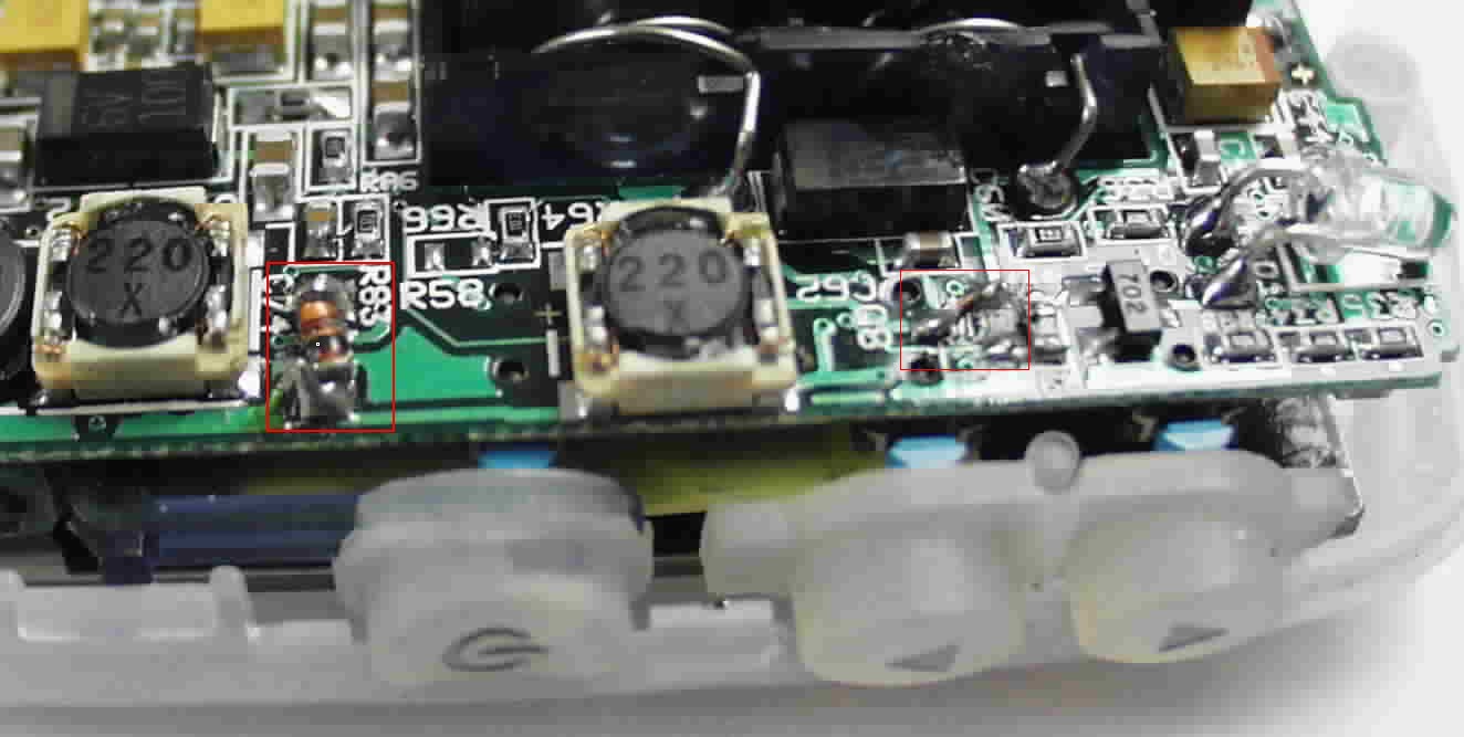
Here is a picture to make the modifications:
The two red
rectangle show the modifications: the left one is the diode already soldered (
sorry, I have no pics before the mods), the right is the unsoldered transistor
place with a small copper line to make a short-circuit. I have a version 9 PCB,
as I know, the version 8 Blue Agendas has a white gizmo (spare cap?) glued at
the diode's place. Therefore here I publish my full ver. 9 PCB picture:
The next issue was to drive the unit over Pin1
with the external voltage. Because the Pin1 connected to other parts of the PCB
also and I can't track the whole line ( as I remember, there is an
resistor-array connection on the other side of the PCB and there is a resistor
at the right side of the red rectangle showing the transistor, etc.) I'm can not
choose any classic solution to charge the battery. I got some circuit to make
this ( thanks!) but each of this solution can result higher than 3.6V at Pin1.
Because I don't know what can this do in the PCB, I choose a quick and dirty
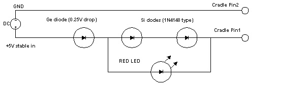
solution : from an stabilized 5V power supply I drive the unit over one Schottky and two Si diode
( the light on the picture is for fun: parallel for this two diodes I
connected a led to see what happened) In this case there are
3 Si + 1 Schottky diode = 3*0.7V+0.2V=2.3 minus the 5V yield maximum 2.7V at the raw power and max
3.4V at Pin1. Because of the resistive part of the diodes, the charging current
also limited somehow. This means that the NiMH accus charged until 1.45V which
seems to be high, but in the real life the unit charges an empty accuset within
few hours and the charge level is 1.3-1.4V. It is depends on what Agenda doing at that time.
This is not a fool-proof solution, because the charging current vary between 100
mA and 0 depending from the accu voltage level and the Agenda power usage. But I think the biggest trouble
can be just not to charge the NiMH's 1000 times just say 500, which is
acceptable to me ( here in Hungary the NiMH 600mA accus costs 3-5 times more
than a good alkaline). Below you can find the schematic of the cradle modification
Sorry, but I forgot to make a picture about the cradle
modification. This is an easy one: if you open the cradle ( 6 crews) and seeing
from the bottom, the right top side of the connector is Pin1 which connected to
the circuit described above, Pin2 is the Ground. The above circuit does not need to make a separate PCB panel, you can solder the diodes one-by-one
. I don't find any good place to assemble the power connector in the cradle, so two wires going from the cradle to the 5V power male connector.
P.S: After half year of usage I find that the Schottky diode is not necessary
when you doesn't leave the Agenda in the cradle for weeks....
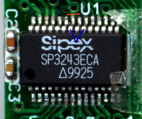
The Serial Cable
The Serial Cable contains a special chip, the Sipex 3243 which convert the Agenda 0-3.3V I/O signal
to the RS-232 minimum -5-+5V and back. In the original version Agenda use the chip "Auto-Online" function to shut
down the transceiver's voltage converter, conserving energy. Unfortunately this function is a simply one: when all the RS232 input
is not driven by the connected computer ( the cable unplugged ) disable all input/output driver and his power converter.
But when the cable is connected the converter working, eating approx. 10 mA. There are additional possibilities to shut down
the converter, for example there is a SHUTDOWN input ( Pin 22 ) which is when low, force the
standby mode ( 1uA! ).
In the original version this pin connected to the 3.3V VCC, therefore just the Auto-Online works. The ideal
solution were if we can drive this pin
by the Agenda's inverted DTR signal - but in this case need to mount to the circuit minimum one transistor and a resistor.
There is an additional solution: We can watch the other side DTR signal: it is connected to Agenda DSR , over a special input pin of
the transceiver - the R2in pin has a normal (inverted) and a special (non-inverted) output, the last one working all the time - therefore if we
cut the SHUTDOWN pin from the VCC and connect to the R2out (pin 22) the unit will go to sleep when the computer DTR is inactive ( -12V) and
arise when become active (+12V). The corresponding circuit is in the serial cable connector, in the picture below you can find the
modifications: the red line shows where you must cut the PCB , the blue one is the Pin 20-Pin22 connection.
The Agenda Network Menu contains special items for this connection: the "MS
Direct Cable Connect" host/guest item. It is not really necessary if you can do
the following:
- locate the mdmhayes.inf file in the %Systemroot%/inf directory and edit this
text file. In the [M2700Reg] section append the following two lines :
HKR, Responses, "<h00>~", 1, 08, 00, 00, 00, 00, 00,
00,00,00,00 ; Server side - the client is requesting a connection
HKR, Responses, "~", 1, 08, 00, 00, 00, 00, 00, 00,00,00,00 ;
Server side - the client is requesting a connection
- save the modification, and delete the corresponding .PNF file ( mdmhayes.pnf
).
Now you can set up new "modem" , the Direct Cable connection on serial port and
attach it to the RAS server (XP: Incoming connections ). In this way from the
Agenda there are no any difference between the Unix/Cisco,etc. and the M$
connection. (The above modification means: when the Direct Cable connection see
the PPP start character "~" start the PPP session with the peer, not playing
with the CLIENT/CLIENTSERVER strings).
If you have a real IP subnet on your Ethernet you can also assign two IP
address ( from the Ethernet IP subnet!) for the PPP connection ; this case
there are without any additional setting you have a routed, full-featured IP
connection to the Agenda.
Connecting over the IRDA port
I was unable to set up it with the core operating system components, so some hacking
needed. There is an excellent tool to making virtual COM port from the IRDA
on W2k/XP at: http://www.ircomm2k.de/ . After
downloading/installing you will have an additional COM port ( in my notebook the
COM6 ). With this extra COM port you can make an additional Direct Cable
connection - and with this method you can set up a PPP connection over the IRDA
port. The driver set the connection speed to 9600 bps, but the measured (bing)
transfer speed vary between 38 and 49 kbps. The service ( Virtual IR COM Port,
Service Program ) at least in my machine not very stable - sometimes after
dropping the connection it drives the
CPU to 100% and after restarting the service manually simply doesn't work. In
this case you can deselect/select the virtual com port listening in the Incoming
Connections list, after this everything working again. After some playing with it
seems to be working perfectly if you never drop the connection, just break the
infra link.


 Full size
 Full size